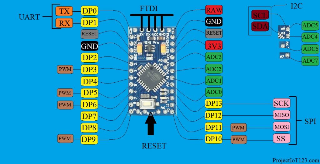

When the digital pin acts as the input it can read the digital sensors. Notice here that the suffix Input / Output is added to the digital pins it is due to the fact that the digital pins of the Arduino PRO MINI can act either as input or an output and the digital pin being the input or the output is determined by the code. The Arduino PRO MINI has total 14 digital Input / Output pins as shown in figure from DP 0 to DP 13. Let us now learn about the pins of the Arduino PRO MINI in some detail. Arduino PRO MINI Digital Input / Output Pins:
#ARDUINO PRO MINI PINOUT DIAGRAM SERIAL#
The USB to Serial UART bridge module as introduced in the previous section is connected to these pins. The FTDI written above is not any interface protocol but it is only used to program the Arduino PRO MINI.

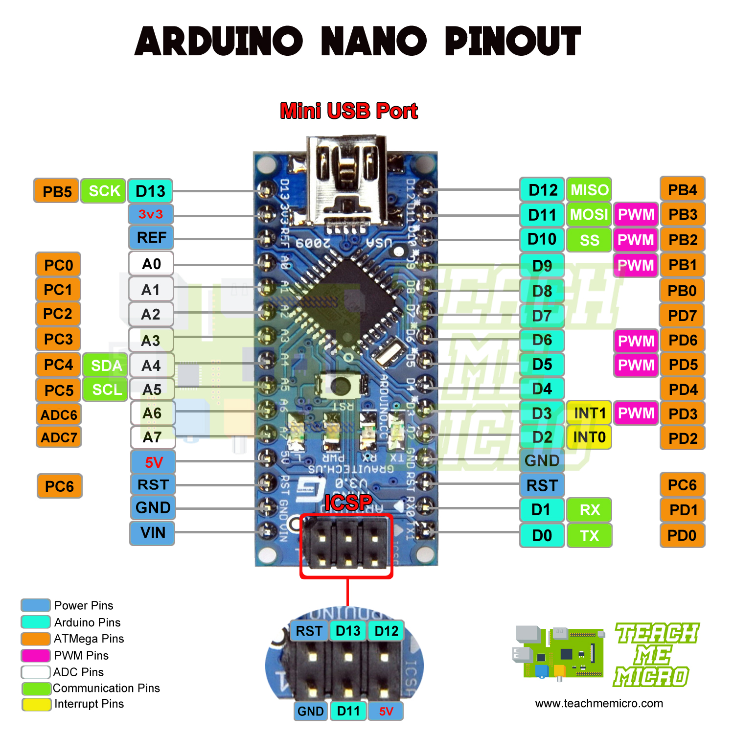
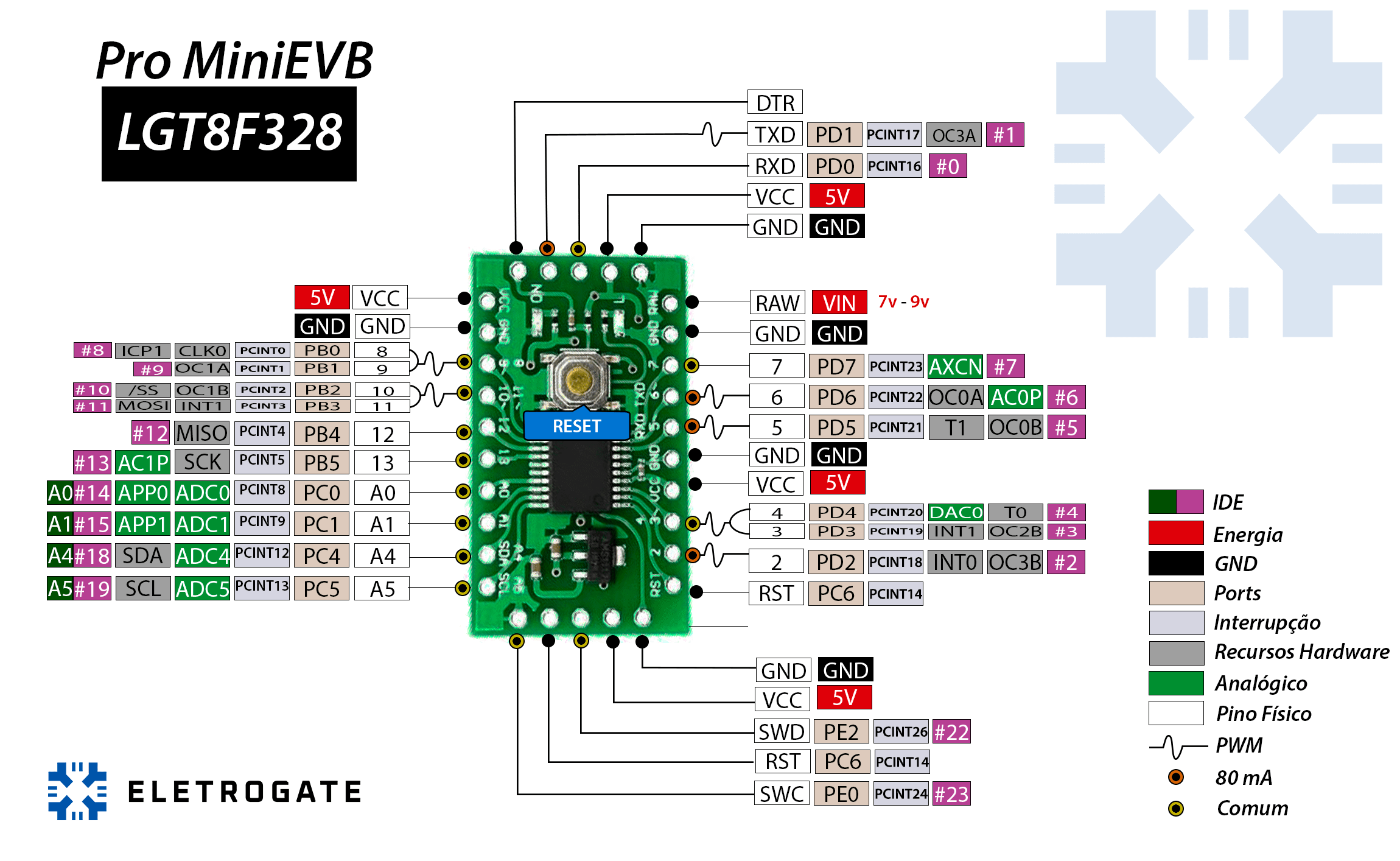
The functionality of these pins is determined by the programming of the Arduino PRO MINI. Notice form the pin description that the digital input / output pin 10, 11 ,12 and 13 act as the Serial Peripheral Interface and the digital input / output pin 0 and 1 acts as the Tx and Rx of the UART respectively and finally the pin number A5 and A4 act as the I2C computer bus. The detailed diagram of the pinout of the Arduino PRO MINI is as shown in the following figure: The PWM phenomenon and the application of these pins will be discussed in the post later. Out of the 14 digital input / output pins 6 of them are the PWM enabled pins. The Arduino PRO MINI has 14 digital input / output pins and 8 Analog input pins. As pointed earlier that the Arduino PRO MINI is based on the same microcontroller IC as that of the Arduino UNO that is ATMEGA328P thus it follows that the pinout and other features of both the boards are essentially the same. This post is designed for the earlier version but all the concepts and points are equally valid for the 5V / 16 MHZ version.īefore diving deep into the discussion let us first have a brief look at the pinout of the Arduino PRO MINI. One is 3V3 / 8 MHz version and the other is the 5V / 16MHz version. Another point worth mentioning here is that the Arduino PRO MINI comes in two versions which are classified on the basis of their Operating voltage and their clock frequencies. The Arduino PRO MINI is almost 1/6 of the size of the Arduino UNO board. Notice in the above image that there is no USB connector and power jack on board. The Arduino PRO MINI microcontroller board looks like the one shown in the following figure: The detailed discussion on this module and programming of the Arduino PRO MINI will follow in the post later. However in order to make programming easier and handy the manufacturers have released a module that acts as the bridge between USB and UART.

Notice here that the Arduino PRO MINI has no USB interface on board which means it cannot be programmed through your laptop USB COMM PORT. Thus it becomes handy to program the Arduino UNO with the help of your computer. The programmer found on board in case of the Arduino UNO is basically the USB to serial data bridge which converts the USB data into the UART and SPI data. In order to make the size smaller the designers has taken out the serial programmer from the Arduino Pro Mini. An important difference between the Arduino UNO and Arduino PRO MINI as pointed out earlier is the Hardware design that is Arduino PRO MINI lacks the on board-programmer. Arduino PRO MINI has 14 digital Input / Output pins out of which 6 are PWM (Pulse Width Modulation) enabled and 8 Analog pins. It should be noted here that all of the communication ports that are found on the Arduino UNO are also available on the Arduino PRO MINI microcontroller development board. The Arduino PRO MINI has one UART (Universal Asynchronous Receiver and Transmitter), one SPI (Serial Peripheral Interface) and one I2C (Inter-Integrated Circuit) computer bus. The main difference lies in the hardware design of the board. That is the Arduino PRO MINI microcontroller development board is designed around the ATMEGA328P microcontroller IC so that most of the features of the Arduino UNO and Arduino PRO MINI are the same. The Arduino PRO MINI microcontroller development board is quite small in size as compared to the more common Arduino UNO but it is based ATEGA328P. Arduino PRO MINI microcontroller development board is the variant of the Arduino UNO microcontroller board with specific perks and quirks.


 0 kommentar(er)
